
Preface
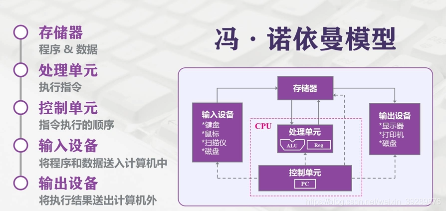
Modern computers still follow the Von Neumann architecture. In this architecture, memory/storage is the key piece: both persistent data and the working space for computation depend on it. In an ideal world, a storage device should have the following properties:
- It should be extremely fast—at least fast enough to keep up with the CPU executing instructions—so the CPU has unlimited room to perform and won’t be bottlenecked by memory.
- It should have a large enough capacity. In the digital era, more and more data needs to be persisted, and storage shouldn’t be constrained by capacity.
- It should be cheap enough. Low cost means all kinds of computers can be equipped with it—i.e., it can reach consumer-grade adoption for most people.
Hierarchical Memory Structure
So, does such an ideal storage device really exist? With today’s chip industry, we can’t satisfy all of the above at the same time—mostly due to cost constraints. That’s why computers adopt a hierarchical memory model like this:

From top to bottom:
-
The fastest to access is the registers, because they’re packaged inside the CPU, and made with the same materials/process as the CPU. So their speed can match the CPU’s, and CPU access to registers is basically zero-latency. But everyone knows the CPU is the pinnacle of human manufacturing—registers are expensive, so their capacity is tiny. Typically, CPU registers are bit-level in size and only store CPU instructions.
-
Next is the CPU’s multi-level cache, also called cache memory. Intel and AMD now both ship three levels: L1, L2, L3. Generally, L1 is per-core “private” memory, L3 is shared, and L2 differs by vendor design. Intel consumer Core uses a shared L2 design, while AMD consumer Ryzen uses a private design. This part is also inside the CPU package, and capacity is still small: L1 and L2 are usually KB-level, and L3 can reach MB-level. For example, Intel 11th-gen Core i5-11400 has 12MB L3, and AMD Ryzen 5600X has 32MB L3 (quietly~ amd yes).
-
Then comes the more familiar RAM, the computer’s main memory, usually called Random Access Memory. It’s internal storage that exchanges data directly with the CPU. It can be read/written at any time and is fast, but it’s volatile—power off and the data is gone. This part is configurable (what people call “adding RAM sticks”), typically GB-level.
-
Finally, there’s the disk. Compared to main memory, disk is about three orders of magnitude slower, so it’s much cheaper and thus much larger in capacity—often TBs or hundreds of GB. SSDs use silicon semiconductor storage, while HDDs use a mechanical arm + head to read sectors on metal platters.

Main Memory
Memory is absolutely critical for OS I/O operations. The vast majority of work happens between user processes and kernel buffers, because memory is faster than disk, and larger than CPU cache. So next, we need to understand some memory-related concepts.
Physical Memory
Physical memory is the real “third layer” mentioned above. It’s plugged into the motherboard and used to load all kinds of programs and data for the CPU to read.
Virtual Memory
So why do we introduce the concept of virtual memory? From a computer organization perspective, physical memory is where applications are loaded. But from an OS perspective, directly operating on physical memory has many limitations.
Because each application requesting memory needs a whole contiguous region, you can end up with situations like this: you open apps one by one, and they fill up physical memory. Then you want to play a game—you need to keep WeChat for voice chat and keep NetEase Cloud Music playing. QQ and Bilibili can be killed. But because NetEase Cloud Music sits in the middle, the game (Honor of Kings) needs one big contiguous block and can’t get it. You end up with “fake full” memory, which is obviously unreasonable.

So, virtual memory comes in. The core idea of virtual memory is: give each program a “contiguous” virtual address space, split that address space into multiple pages (page) with contiguous address ranges, and map these pages to physical memory. During program execution, pages are dynamically mapped into physical memory. When a program references an address range that is in physical memory, the hardware immediately performs the necessary mapping; when it references an address range not in physical memory, the OS is responsible for loading the missing part into physical memory and re-executing the failed instruction.
The virtual address space is divided into fixed-size units called pages (page), and the corresponding units in physical memory are page frames (page frame). Generally they’re the same size—like 4KB in the figure above—but in real systems it can range from 512 bytes up to 1GB. This is the paging technique of virtual memory. Since it’s virtual address space, each process gets 4GB (on a 32-bit architecture). Of course, it’s impossible to allocate 4GB of physical memory to every running process. So there’s also a technique called swapping: during execution, only the currently used memory is mapped/allocated; data that isn’t used temporarily is written back to disk as a copy, and read back into memory when needed—dynamically swapping data between disk and memory.

One benefit here is: the memory a user program requests is virtual memory. When virtual memory maps to physical memory, the physical memory does not need to be contiguous. This brings us to the Memory Management Unit (MMU): when accessing virtual memory, the CPU sends virtual addresses to the MMU via the address bus; the MMU maps the virtual address to a physical address, then accesses physical memory via the memory bus.
Finally, there’s one more concept to know: the Translation Lookaside Buffer (TLB), also called the “fast table.” It accelerates virtual-to-physical address translation. Because of paging, the page table is typically stored in a fixed region of memory, which means a process accessing memory via the MMU incurs an extra memory access compared to direct memory access—performance can drop by at least half. So we introduce an acceleration mechanism: the TLB. You can think of the TLB as a cache of the page table, storing the most frequently accessed page table entries. Since it’s usually implemented in hardware, it’s extremely fast. When the MMU receives a virtual address, it typically queries the hardware TLB first for the corresponding page table entry. If it hits and the access is legal, it directly returns the physical page frame number from the TLB. If it misses, it falls through to the in-memory page table, and then replaces one of the existing TLB entries with the newly fetched page table entry for future hits.
I/O Buffer
Since I’ll introduce I/O later, while we’re talking about memory, let me mention buffers as well. Linux read() and write() are the most basic I/O system calls, and there’s a buffer between these two system calls. The so-called I/O buffer is a layer of buffering between kernel space (I’ll cover this next time) and peripherals like disks and NICs, used to improve read/write performance.
Common ones during transfer are the Kernel Buffer Cache (reading from disk) and Socket Cache (writing to the NIC). The former is a collective term for Page Cache and Buffer Cache. One thing worth noting: people like to call the Page Cache disk cache, but this storage is actually in memory—even though it has “disk” in the name…
Why do we have this “disk cache”? Because reading/writing memory is much faster than reading/writing disk. If we can turn disk I/O into memory I/O, efficiency improves a lot. If RAM and disk had the same cost per capacity, we wouldn’t have so many headaches—but reality is harsh. Also, program execution has locality: you don’t need to access all data every time, and there’s usually hot data—data accessed recently has a high probability of being accessed again soon. So OS designers created the disk cache to cache recently accessed data, and when space is insufficient, it uses LRU to evict the least recently used cache entries.
The flow is: when reading disk data, check the Page Cache first. If the data exists, return it directly. If not, read from disk, then cache it in the Page Cache for next time. Lots of research shows that after reading a block, adjacent blocks are very likely to be read next, so the Page Cache provides read-ahead: it secretly reads a bit more each time. If it’s not accessed for a long time, it’ll be evicted anyway; if it hits, the payoff is huge.
Based on the above, it’s not hard to see the downside of Page Cache: these benefits are mostly under small file reads (typically program working data). If the I/O file is very large, Page Cache doesn’t help much, because the disk cache space gets filled quickly, then evicted, filled, evicted… Since the file is huge, the probability of re-accessing the same data is very low. Frequent eviction and writes not only bring no time benefit, they can also cause performance issues (large files are usually GB-level).
Here’s a supplement about Buffer Cache. In fact, Page Cache caches at the virtual-memory page granularity, while Buffer Cache caches finer-grained device blocks. That means each read/copy can end up with two copies—redundant and inefficient. Worse, it can cause inconsistency issues. To avoid this, all filesystem-based disk write operations need to call update_vm_cache(), which updates the Buffer Cache changes into the Page Cache after write. Because of these design drawbacks, after Linux 2.4 the kernel unified the two: Buffer Cache no longer exists independently, but is merged into Page Cache. That’s why you often see people discussing the buff/cache in the figure below—this is the collective term for Page Cache and Buffer Cache. They’re already in the same place, so there’s no need to overthink it.

Epilogue
There’s actually a lot more in memory topics—like multi-level page tables, inverted page tables, and page replacement algorithms. Due to length and focus, I’ll stop here. Keeping it shorter makes it easier to digest. Hope this helps a bit.
All articles in this blog, unless otherwise stated, are licensed under @Oreoft . Please indicate the source when reprinting!